Online Instructions for the
HES Kit.
Download The Fully
Illustrated Instruction Manual Here
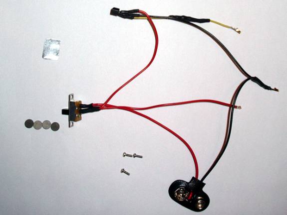
Kit contents:
A pre-wired sensor and wiring harness.
A mounting bracket.
Three short mounting screws (2 needed, 1 extra).
Four 1/8th inch magnets.
3 Extra Molex connections (in case replacement is needed)
This Instruction Guide.
Tools Needed:
One set of Allen wrenches
One small Phillips screwdriver
Small amount of your favorite glue/epoxy.
Approx. Time to complete installation:
25 minutes (plus any added drying time for your glue)
Important: Before
you start the steps below,
please make sure
your marker is degassed and off!!!
Installing the sensor and wiring:
1.) Open up the grip frame of your Intimidator to expose the internals. If you are not sure on this procedure, refer to the instructions in the Intimidator manual. You can find a link to the manuals online under “Useful Links”.
2.) Disconnect the 9-Volt battery from the battery connector.
3.) Using the small Phillips screwdriver, remove the two small Phillips head screws that hold the stock microswitch in place.
4.) Lift the microswitch out of the way. Now follow the blue and yellow wires from the switch back to the 14 point wiring harness that connects to the board.
5.) Using a small tool (a small screwdriver or a small Allen wrench works well), gently lift the plastic tab for the blue lead slightly up. Once done, gently pull the blue wire and Molex connector out of the black plastic harness. It is not used in the HES installation.
6.) Repeat Step 5 for the yellow microswitch lead. It is very important to remember which one the yellow lead went into. You may want to lightly scratch a “Y” into the black plastic connector right below that pin position as an aide to remember.
7.)
Locate the
yellow lead on the Hall Effect Sensor (HES), and push the gold connector into
the harness position you removed the
yellow
microswitch lead. Make sure it has
seated all the way. You may need to press the black tab you lifted down
slightly to make sure it’s a snug fit.
8.) Locate the on/off switch on your marker, and remove the two retaining Phillips screws on each side of it.
9.) Trace the red lead from the switch back to the 14 point wiring harness. Using the same method you used in Step 5 and 6, remove the red lead from the harness.
10.) Locate the red lead on the HES, and press it into the position you removed the old red lead from.
11.) Locate the black lead that goes from the battery connector to the 14 point wiring. Using the methods above, remove it from the wiring harness.
12.) Place the black lead from the HES in its position.
13.) At this point, the old switch, battery connector and on/off switch wiring are separate from the marker. Store them in the antistatic bag this kit came in, in case you wish to reuse them in the future.
14.) Using the shorter trigger screws provided in the kit, screw the HES mounting bracket into place where the microswitch previously rested.
15.) Mount the new on/off switch back on the grip using the original screws.
Installing the Magnets:
1.) Using your glue of choice, glue the magnet with the “X” on one side onto the middle set screw of the trigger. This will be the magnet that activates the HES.
IMPORTANT! The “X” is the glue side!!! If you use the wrong side, the sensor will not be tripped!!
2.) Glue another magnet to the top set screw. It is best to have the magnets “facing” the same way. For example, both “south” sides are the glue side.
3.) Glue the third magnet to the pole the trigger spring rested against. Make sure the side you glue is the same as the other two. This will allow the magnets to repel each other, and return the trigger.
4.) If you find the distance too great, or the trigger too slow, you can add the fourth (extra) magnet to the rear return magnet. This will strengthen the field and remove some of the distance.
IMPORTANT! The magnets should not touch when the
trigger is pulled! If they do, you run the risk of one being broken loose from
the glue.
Positioning and Gluing the Sensor:
1.) With all the wiring and magnets in place, reconnect your battery and turn your marker on.
2.) Once it has finished booting up, take the sensor and press against the mount and position it in the way you find best. At this time you may want to adjust and pull the trigger to get the optimum placement as you like.
3.) Once you are satisfied with the position, apply a small amount of glue to the bottom (blank) side of the sensor and position it on the mounting bracket.
4.) Once dry, pull the trigger and recheck everything is functioning as normal.
5.) Re-assemble the marker.
Congratulations!
You installed the kit!
Now go fine tune
your trigger and have fun!
Tips and Tricks for Mounting the Sensor:
Because everyone has their own preference of trigger feel, each HES setup will differ as well. Most people that like a “medium” pull have found that placing the sensor at a 30-to-45-degree angle, and slightly down from the magnet works best for them.
If you like a “sloppy” trigger, you may find that this is not the best setup for you. In this case, most people have found that bending the bracket at a 90-degree angle, and fixing the sensor on the bend allows for a more forgiving setup. This provides the entire face of the sensor to the magnetic field, allowing a broader area for actuation. If you try the 90-degree bend, and are not happy with it, simply hammer the bracket back flat.
If you prefer a very short trigger pull, the best placement is straight across and parallel to the magnet. The magnet and sensor combination selected for this kit allows you to give a pull as short as about 1/8th of an inch.
Another trick is to glue the actuation magnet offset from the center of the setscrew. This will allow the magnet to pass over the face of the sensor to activation. If you use this method, make sure to set the trigger stop (bottom) setscrew to stop the trigger travel before the middle setscrew hits the sensor. If it does, it could pop the sensor loose from the bracket, or worse, damage the sensor.
Remember, the whole key to the setup is time and fine-tuning. With patience, you will find a point at which the kit works best for your trigger style.
Troubleshooting:
|
Problem |
Possible Cause |
Possible
Solution |
|
The
sensor will not trip. |
Sensor
Magnet glued on wrong side. Magnet
too far away. Yellow
Lead in wrong pin. |
Check
middle setscrew magnet polarity. Check
magnet-sensor distance. Make
sure Yellow Lead is correct. |
|
Sensor
will not release. |
Sensor
Magnet too close. |
Adjust
trigger to allow more distance from sensor on release. |
|
Marker
will not turn on. |
Red/Black
Lead(s) in wrong pins(s) |
Make
sure Red/Black Lead(s) are correct. |
|
Wire
Connectors won’t stay in. |
Black
tab on black Molex connector raised. |
Gently
push down the black tabs to hold the connector in. |
|
Trigger
Return to slow/weak. |
Return
Magnets too far apart |
Adjust
return setscrew to remove distance between magnets Install
fourth (extra) magnet to strengthen field/remove distance. |
|
Trigger
pull to hard. |
Return
Magnets too close. |
Adjust
return setscrew to add distance between magnets Remove
fourth (extra) magnet to weaken field/add distance. |
Kit components and their part numbers:
Hall Effect Sensor: Panasonic DN6848
Magnets
Old Kit: Radio Shack 64-1895
New Kit: Emovendo Neodymium N48
On/Off Switch: E-Switch EG1201A
Screws: Generic 3/16th 0/80 Pan Head
Connectors: Molex 50394-8100
Contact Info:
If you are still having difficulties
installing or diagnosing a problem, or just have a general question, feel free
to contact me. Methods of contact are:
Email:
dwilson8@austin.rr.com
Online:
http://www.jeffwilson.net/HES
Newsgroups: PBNation.com - CounterMeasure
FlagStation.com –
CounterMeasure
Liability:
By using this kit, or building your own, you agree to not
hold me (David Wilson) responsible for any type of direct or indirect liability
from the use of this kit/design. You also agree to not hold me responsible for
any damage due to misuse, abuse, incorrect installation, or
modifications of the kit, or any damage this kit causes to any other
components. This kit is provided only for the sake of those that wish to try or
use the Hall Effect upgrade I have provided free on-line, but are not
comfortable with building their own.